Explanation of terms in the operation manual of combined sel
Explanation of terms in the operation manual of combined self-supporting crane
Axial load: the total vertical force acting on the supporting structure. The calculation formula is: axial load = (total weight of crane) + (design factor X lifting load weight)
Main beam length: the total length of the main beam. Note: the working length of the main beam or the coverage of the hook on the beam is smaller than the total length of the main beam.
Buffer device: a spacer set between two main beams (or hoist trolleys) in the fixed rail to prevent concentrated overload between hanger points, which limits the minimum distance between main beams or hoists.
Column: the column of the combined self-supporting crane is the "legs" of the combined crane, which is composed of square tubes. The crane stands on these "legs".
Deflection: the difference in rail deflection between an unloaded crane and a fully loaded crane is usually calculated in millimeters. In general, Gaobo's design is that the beam crane is L / 450, l = support center distance or span.
Beam: a horizontal beam in the supporting structure of the combined self-supporting crane, which is composed of two back-to-back channel steel, and the fixed rail is suspended here.
Total height (OAH): the distance from the ground to the highest point of the crane (including metal components).
Span (main beam): the distance between the center lines of fixed profile rails. The span must be distinguished from the total length of the main beam (oal), which is longer than the span. Calculation formula (using pre crane): span = {girder length - (2 x girder cantilever length)}
Support Center: refers to the distance between the center lines of two columns or the hangers along the fixed profile rail. The center of support determines what type of profile rail needs to be used.
Supporting structure: for the combined self-supporting crane, the supporting structure refers to the supporting component, also known as the gate post or terminal frame, which is composed of columns and beams. For a set of combined suspension crane system, the supporting structure refers to the roof, including truss frame, longitudinal beam, column, etc., where the crane is suspended.
Hoist trolley height (TS): for self-supporting cranes, it refers to the height from the top of the hoist trolley pin shaft (the hoist is hung below the pin shaft) to the ground.

 DEMAGE Electric Chain Hoist
 DEMAGE hoist
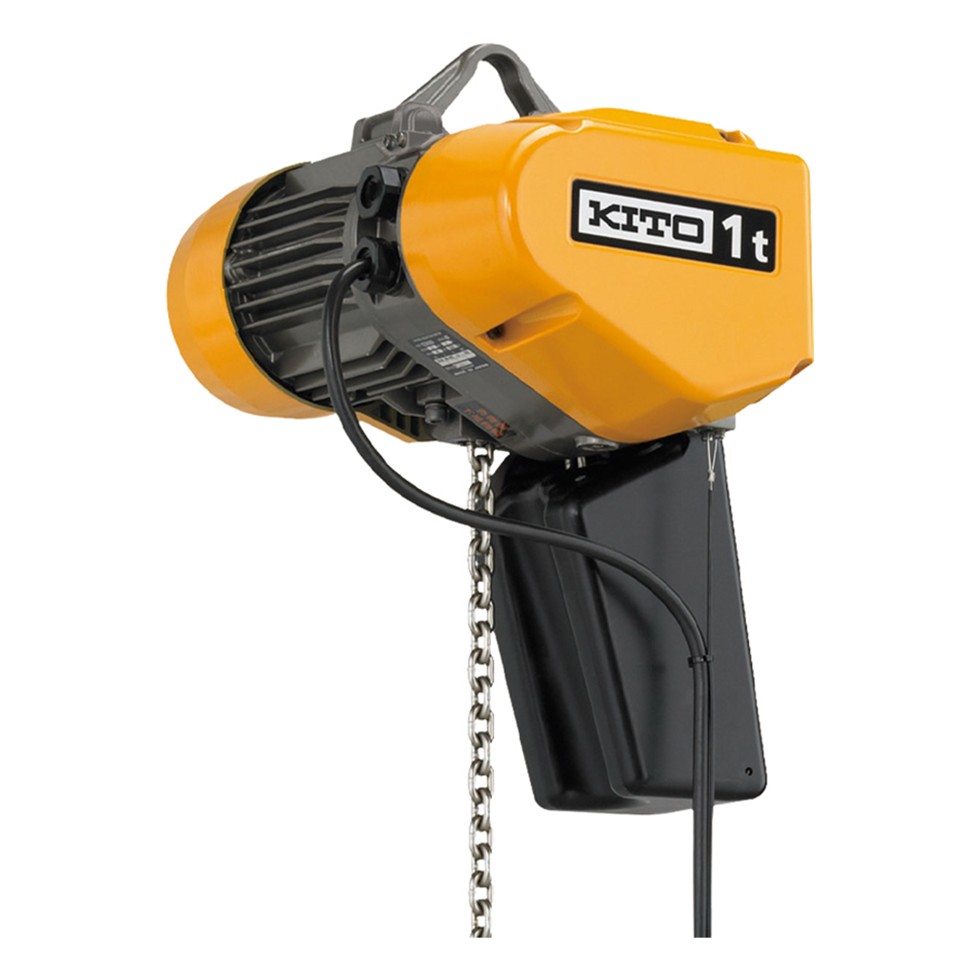
 KITO EQ Series Electric Chain Hoist for Sale
 Demag chain hoists
 DRS wheel block system
